| TradeSalon® | Pipeline And Cable Location |
|---|
| 
| 
| 
|
| PCL2012 | PCL2011 | PCL2010 | PCL2009 |

| I am a cable maintenance worker, I dream for many years is whether there is a kind of instrument: Can find the path to run the cable? Identification of the cable run can be solved? High-voltage cables can be tested without fault? Oh, hard! Hard! Hard! Hard! | 
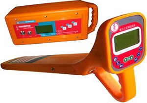
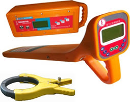
| Look! Cable test in the all-around champion which has beening developed over 5 years, The PCL2012 cable integrated detectors - cable routing, identification, find fault, a multifunctional integrated machine. | 
|
|
A new era in the field of cable detection. Five features of the instrument:
|
|
Find the path to run cable
Charged with PCL2012 can easily solve the problem to find the cable path. To live under test will measure the coupling clamp cable clamp on the target by coupling the transmitter to generate the cable coupling signal. Path along the cable can receive the signal applied to the transmitter. Such work can detect the cable length is not less than 3 km. The receiver equipment can detect the 50Hz frequency signal cable run, this work live for the distinction between cable and the cable is charged is not practical, in this manner without the use of launchers. Blind testing underground cable In some cases, the operator can not come close to direct cable connection or use of the coupling clamp, then you can use the built-in sensor transmitter antenna to transmit output signal, the signal is sensitive to the measured up to locate underground cable detection. Such work can detect the depth of not less than 2 meters cable. Find Buried cable fault The instrument can be applied step voltage method to determine the buried cable insulation resistance of less than 2M�� cable fault; signal strength method can also be used to determine open circuit cable fault. PCL2012 underground cable tester has changed the traditional concept of cable fault location, without high voltage test equipment, without the use of AC power, no analysis of the waveform, the wiring is simple, using a look that will. Identification of running cables Live cable identification: the transmitter card through the launch of the coupling clamp on the cable, exposing the other end of the cable clamp connection at the receiver coupled with the receiver and the cable card. At this point the size of the signal can determine which one to increase the signal cable. (This method requires a special receiver with multi-clamp.) Receiver and transmitter and receiver combination pliers, you can judge for cable charged state. |
Operating characteristics
Transmitters, receivers, coupled clamp ( launch ), A-frame Option: Coupling clamp ( receiver ), car charger | Specifications
|
| 
| 
| 
|
|
Model: PCL2011
Cable fault Locator consists:
| 
| |
| 
| |
|
|
|
Technical parameters
| 
|
Cable Line Locator Standard configuration Listing
| Name | Model
| Quantity
| Remark
| Specification
| Cable line fault tester
| PCL2011
| 1
| Standard
| Multifunction, Accurately fixed, Path analyzer
| PCL2011
| 2
| Standard | 50 million times Gain
| High Voltage Acquisition Box
| PCL2011
| 1 | Standard
| Voltage or Current Two testing methods
| Probe
| 2
| Standard
| Headphones
| 2
| Standard
| Military High impedance Headphones
| Special Discharge Ball Gap
| 1
| Standard
| "3000V/mm Continuously adjustable"
| Test line
| 1
| Standard
| Rubber cord, Diameter 1.6 mm2
| Signal line
| 2
| Standard
| Power Line
| 1
| Standard
| 220V/3A
| High-voltage pulse Capacitance
| CHM
| 1
| Standard
| 30KV/1��F
| Option list ( customer choice )
| Name
| Model
| Quantity
| Remark
| Specification
| AC and DC Light testing transformer
| YD-3-50
| 1
| Optional
| 3KVA/AC 50KV DC 70KV
| transformer box
| YD
| 1
| Optional
| 3KVA
| | |||||||||||||||||||||
 |
Instrument function
depth with cable shows, current shows backlight function to adapt to night operations can find up-to-ground insulation failure 2MΩ Built-in ohmmeter measure the cable loop resistance portable lightweight, easy to use, quick to find large screen LCD graphic display, without earphone test path with the cable locating and fault finding two functions Built-in rechargeable battery, the test is not required electricity all-digital positioning system, showing a clear, reliable positioning 
|
Model: PCL2010 |
|
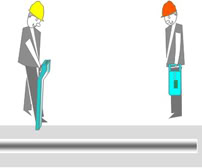
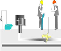
Signal comparison
Will signal to the fault phase, the signal current at the fault point of leakage (short circuit) or blocking (open), then the signal at the fault point will change, according to the fault point of the signal changes to determine the point of failure This test method is suitable for open-circuit cable fault and ground leakage fault, the transmitter signal is applied to the cable fault phase, the receiver elected to the "peak method" track forward along the cable, when the signal has sharply reduced or Ah then disappear (sudden jump point) a lot, they can identify the fault location. | 
| 
| ||||||
|
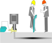
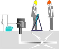
Step voltage method
Before the start of the fault in positioning both ends of the cable disconnected from the system, and then pulse voltage applied to the fault between the cable and the earth. Pulse voltage at the fault point on the generation and discharge, the current generated by the fault at the launch point of the grounding return. Leakage current to generate a fault point voltage gradient, by measuring the voltage gradient to find the point of failure. This test method is suitable for cable-to-ground fault, imposed by a special transmitter on the frequency of high-voltage cable, the voltage generated by the cable after cable fault current into the ground, the voltage gradient is created around the point of failure, through the 'A' word frame the two electrode potentials measured along the cable route changes. When close to the point of failure, the potential difference will increase rapidly, and reached the maximum before approaching the point of failure, move signals big - small - big change point, the minimum point of this change is the point of failure. |
| |||||||
|
| ||||||||||||||||||
|
Attention As PCL2010 Buried cable fault tester developed to expand the concept of a sentinel, with PCL2010 Buried Cable Fault Location Tester will be very convenient, very practical. But PCL2010 buried cable fault tester can not fully replace the DZY-2000 cable fault tester, its use will be subject to certain conditions, such as non-buried cable and high impedance fault, not a fault, such as measuring the approximate distance . The combination of the two best positioning. According to experts, a large number of cable test proved, PCL2010 buried cable fault tester PCL2012 Cable Fault intelligent cable fault tester is the best combination of tests, this combination can be a great play to their strengths, fast and accurate 100% search measuring point of failure. By the user friendly cable test instrument called the "golden combination." Hope that funds permitting, the user will purchase the two instruments together, solve the cable test in a corner. |
|
We mainly offer electrical power system measuring instrument, communication
equipment development development, production, sale and technical
service primarily.
Its goal uses the domestic and foreign widespread close relations, depends upon the institutions of higher learning the scientific research achievement, the application world advanced technology for safeguards our country electric power, the communication equipment normal operation but provides the quick service.We are engaged in the electric cable reflectoscope reflector the research to have more than 10 years history, the product has sold nearly thousand, has obtained the good social efficiency and the economic efficiency. Has the very high prestige in the general electrical power system user. 
|
|
|
| ||||||
Transmitter:
Chooses the fitting:
|
Receiver
| ||||||
| 
| 
|
|---|
| 
|
| 
| 
|
|---|
|

| © | TradeSalon | ® |